Using a buffer to write sensor values to a SD card at 2000samples/sec+.
The time interval is 250um = 4000 samples/sec.
This works but produces alot of noise. Reading the Mic directly from A0.
Using SD Shield and SD FAT beta library (though the other one works) but code says must be newest version.
Define SD SS pin = 8 in the fastLogger sketch. Define the pins the SD library is ridiculous.
Works with the JAVA wav creator and reads hex as its faster.
Tuesday, 4 October 2011

Thursday, 29 September 2011
DrumHero Game
Concept:
Using the 8x8 RainbowDuino LED matrix and various vibration sensors and buttons to create a guitar hero style game for playing an electronic drumkit. This is a working example of several research areas including timers, interrupts, sensor readings, I2C bus
Mapping the LED Matrix:
To be able to manipulate the matrix it is represented in code by a 2D array containing on/off values (int 0 or 1)
int displayGrid[LEDs/2][LEDs]; // the LED matrix
initially this is initialised with all values as false. This creates a 4x8 matrix. We are dealing with 4 column as that is reasonable for a drumkit and allows each channel to occupy 2 LED's. This is much easier to view.
From here the Rainbow duino's buffer is written by reading each value of the array and colouring in the matching pixel.
void refreshDisplay() {
sendCMD(0x10, CMD_CLEAR_PAPER);
for(int x=0; x<LEDs/2; x++) {
for (int y=0; y<LEDs; y++) {
if (displayGrid[x][y] == 1) {
if (y==0) {
sendCMD(0x10, CMD_SET_INK, 0xF, 0x0, 0);
} else {
//Serial.print("on");
sendCMD(0x10, CMD_SET_INK, 0xD, 0xF, 0x00);
}
sendCMD(0x10, CMD_DRAW_PIXEL, toByte(x*2), toByte(y));
sendCMD(0x10, CMD_DRAW_PIXEL, toByte(x*2+1), toByte(y));
}
}
//sendCMD(0x10, CMD_CLEAR_PAPER);
}
sendCMD(0x10, CMD_SWAP_BUF);
}
Creating the Tempo
The game is controlled by an internal metronone that keeps tack of the beat. This is achieved through a hardware timer "TimeOne.h". Using a timer is the only way to accurately produce a tempo, using millis() would be inaccurate as other parts of the code could hold the program up.
Timer1.initialize(500000); // initialise timer1, and set a 1/2 second period
Once the timer is setup we attach an interrupt that calls a method every time the timer ticks.
Timer1.attachInterrupt(callback); // attaches callback() as a timer overflow interrupt
By doing this we ensure we catch every tick of the timer and therefore maintain a constant beat. This also allows fine grain control over tempo.
In the callback() method we increase the beatCount by one and let the program know that the counters needs to be moved. Callback method should be as simple as possible to not hold up other parts of the code.
void callback()
{
beatCount++;
moveCounters = true;
}
Controlling each Channel
For the moment each channel display dots at a certain freq., simulating a drum kit rhythm.
Each tick of the timer represents a
Semi quaver (or 16th note). = 1 timer tick
Quaver = 8th note = 2 timer ticks
Crotchet = 1/4 note = 4 timer ticks
Minum = 1/2 note = 8 timer ticks
Whole = 1 = 16 timer ticks
The main loop checks to see what the current beat count and checks to see if each channels note duration requires an action.
The counters for each channel are controlled by two methods. One that starts a pulse at the top LED of the column and another than scans each column and moves and pulses down 1 row. Every tick of the timer results in all counters being moved down a row. The frequency is controlled by starting the column at different times.
if (moveCounters) { // if the timer has ticked over
for (int x=0; x<channels; x++){ // for each channel
updateCol(x); // update the current counters
if (beatCount % delays[x] == 0) { //if a new counter is needed
startCol(x); // create a counter at the top of the col
}
}
refreshDisplay();
moveCounters = false; // reset flag for next timer tick
}
void updateCol(int col) {
for (int y=0; y<LEDs; y++) { // for each row in the col
if (displayGrid[col][y]) { // if this LED is on
displayGrid[col][y] = false; // turn it off
if (y>0) { // if this is not the bottom row
displayGrid[col][y-1] = true; // turn on the LED under
}
}
}
}
void startCol(int col) {
displayGrid[col][LEDs-1] = true; // turn on the top LED
}
With a few adjustments to the display method to do some colors you endup with the following...

Using the 8x8 RainbowDuino LED matrix and various vibration sensors and buttons to create a guitar hero style game for playing an electronic drumkit. This is a working example of several research areas including timers, interrupts, sensor readings, I2C bus
Mapping the LED Matrix:
To be able to manipulate the matrix it is represented in code by a 2D array containing on/off values (int 0 or 1)
int displayGrid[LEDs/2][LEDs]; // the LED matrix
initially this is initialised with all values as false. This creates a 4x8 matrix. We are dealing with 4 column as that is reasonable for a drumkit and allows each channel to occupy 2 LED's. This is much easier to view.
From here the Rainbow duino's buffer is written by reading each value of the array and colouring in the matching pixel.
void refreshDisplay() {
sendCMD(0x10, CMD_CLEAR_PAPER);
for(int x=0; x<LEDs/2; x++) {
for (int y=0; y<LEDs; y++) {
if (displayGrid[x][y] == 1) {
if (y==0) {
sendCMD(0x10, CMD_SET_INK, 0xF, 0x0, 0);
} else {
//Serial.print("on");
sendCMD(0x10, CMD_SET_INK, 0xD, 0xF, 0x00);
}
sendCMD(0x10, CMD_DRAW_PIXEL, toByte(x*2), toByte(y));
sendCMD(0x10, CMD_DRAW_PIXEL, toByte(x*2+1), toByte(y));
}
}
//sendCMD(0x10, CMD_CLEAR_PAPER);
}
sendCMD(0x10, CMD_SWAP_BUF);
}
Creating the Tempo
The game is controlled by an internal metronone that keeps tack of the beat. This is achieved through a hardware timer "TimeOne.h". Using a timer is the only way to accurately produce a tempo, using millis() would be inaccurate as other parts of the code could hold the program up.
Timer1.initialize(500000); // initialise timer1, and set a 1/2 second period
Once the timer is setup we attach an interrupt that calls a method every time the timer ticks.
Timer1.attachInterrupt(callback); // attaches callback() as a timer overflow interrupt
By doing this we ensure we catch every tick of the timer and therefore maintain a constant beat. This also allows fine grain control over tempo.
In the callback() method we increase the beatCount by one and let the program know that the counters needs to be moved. Callback method should be as simple as possible to not hold up other parts of the code.
void callback()
{
beatCount++;
moveCounters = true;
}
Controlling each Channel
For the moment each channel display dots at a certain freq., simulating a drum kit rhythm.
Each tick of the timer represents a
Semi quaver (or 16th note). = 1 timer tick
Quaver = 8th note = 2 timer ticks
Crotchet = 1/4 note = 4 timer ticks
Minum = 1/2 note = 8 timer ticks
Whole = 1 = 16 timer ticks
The main loop checks to see what the current beat count and checks to see if each channels note duration requires an action.
The counters for each channel are controlled by two methods. One that starts a pulse at the top LED of the column and another than scans each column and moves and pulses down 1 row. Every tick of the timer results in all counters being moved down a row. The frequency is controlled by starting the column at different times.
if (moveCounters) { // if the timer has ticked over
for (int x=0; x<channels; x++){ // for each channel
updateCol(x); // update the current counters
if (beatCount % delays[x] == 0) { //if a new counter is needed
startCol(x); // create a counter at the top of the col
}
}
refreshDisplay();
moveCounters = false; // reset flag for next timer tick
}
void updateCol(int col) {
for (int y=0; y<LEDs; y++) { // for each row in the col
if (displayGrid[col][y]) { // if this LED is on
displayGrid[col][y] = false; // turn it off
if (y>0) { // if this is not the bottom row
displayGrid[col][y-1] = true; // turn on the LED under
}
}
}
}
void startCol(int col) {
displayGrid[col][LEDs-1] = true; // turn on the top LED
}
With a few adjustments to the display method to do some colors you endup with the following...

Mic Based Interrupts
Problem:
We need to be able to wake the Arduino when the koala starts calling. The initial test is a volume test. We want the Arduino to wake up when the mic registers a load noise.
To wake the Arduino from sleep an interrupt must be generated and sent to pin 2 or 3.
Although the attach interrupt method allows various parameters to be set for the interrupt (high, low, faling etc) in any mode except "Idle" only Low can be used.
This poses a problem as we need to generate a low signal when the mic reading reaches a certain threshold. Also, as LOW is defined as 0-2V the ambient reading from the mic is actually a LOW signal and it continually wakes the Arduino. Pulling the PIN high with a pull-up resistor pulls it high, but only while nothing is connected. Once the sensor is plugged back in the pin reads normal values. Though in some cases (sound sensor) the pull-up resistor affected the reading.
Solution:
Using and operational pre-amp to set a threshold voltage and generate a low signal when the signal crosses the threshold. An Operational Amplifier (op-amp) is designed to amplify the difference between the V+ and V- input pins. Since the amplifier has very high gain, in this configuration its output is either fully on, or fully off, depending on whether the input (in this case on V-) is greater than, or less than, the reference voltage we put on V+. I am using the LM358

LM358
PIN1 to Arduino interrupt pin. This output will snap low when the input exceeds the reference voltage.
PIN 2 to Mic Signal Output. This is the signal we will monitor
PIN3 to POT signal Out. The pot provides an adjustable reference voltage.
PIN 4 to ground
PIN 5, 6, 7 provide a second input
PIN 8 5V Power supply
Both Mic and Pot are connected through pull-up resistors. Once a threshold V has been calculated we might replace the pot with resistors and hard wire it in.
We need to be able to wake the Arduino when the koala starts calling. The initial test is a volume test. We want the Arduino to wake up when the mic registers a load noise.
To wake the Arduino from sleep an interrupt must be generated and sent to pin 2 or 3.
Although the attach interrupt method allows various parameters to be set for the interrupt (high, low, faling etc) in any mode except "Idle" only Low can be used.
This poses a problem as we need to generate a low signal when the mic reading reaches a certain threshold. Also, as LOW is defined as 0-2V the ambient reading from the mic is actually a LOW signal and it continually wakes the Arduino. Pulling the PIN high with a pull-up resistor pulls it high, but only while nothing is connected. Once the sensor is plugged back in the pin reads normal values. Though in some cases (sound sensor) the pull-up resistor affected the reading.
Solution:
Using and operational pre-amp to set a threshold voltage and generate a low signal when the signal crosses the threshold. An Operational Amplifier (op-amp) is designed to amplify the difference between the V+ and V- input pins. Since the amplifier has very high gain, in this configuration its output is either fully on, or fully off, depending on whether the input (in this case on V-) is greater than, or less than, the reference voltage we put on V+. I am using the LM358

PIN1 to Arduino interrupt pin. This output will snap low when the input exceeds the reference voltage.
PIN 2 to Mic Signal Output. This is the signal we will monitor
PIN3 to POT signal Out. The pot provides an adjustable reference voltage.
PIN 4 to ground
PIN 5, 6, 7 provide a second input
PIN 8 5V Power supply
Both Mic and Pot are connected through pull-up resistors. Once a threshold V has been calculated we might replace the pot with resistors and hard wire it in.
RainbowDuino
The Rainbowduino board is an Arduino compatible controller board with professional LED driving capacity. It will drive an 8x8 RGB Led Matrix.
Tech Specs:
- No external circuit required, plug and shine!
- 24 constant current channels of 120mA each
- 8 super source driver channel of 500mA each
- Wide output voltage adaption from 6.5V-12VDC (runs off Arduino 5V)
- Dedicated GPIO and ADC
- Hardware UART and I2C communication
To get the Rainbowduino up and running some firmware needs to be uploaded to the device.
There are several versions available however the simplest seems to be "RainbowDuino Firmware Version 3"
http://code.google.com/p/rainbowduino-firmware/
Uploading the Firmware:
There are several ways to go about doing this - via Arduino, via Xbee USB. Via Arduino seems the simplest.
Step 1:
Make sure that your Arduino has no software running. To erase any code, flash the processor with the following void code:
void setup(){
}
void loop(){
}
Step 2:
Connections:
Flashing the firmware requires the serial connection so connect:
Rainbowduino -- > Arduino
RX 0/RX
TX 1/TX
DTR Reset
VCC 5V
GND GND
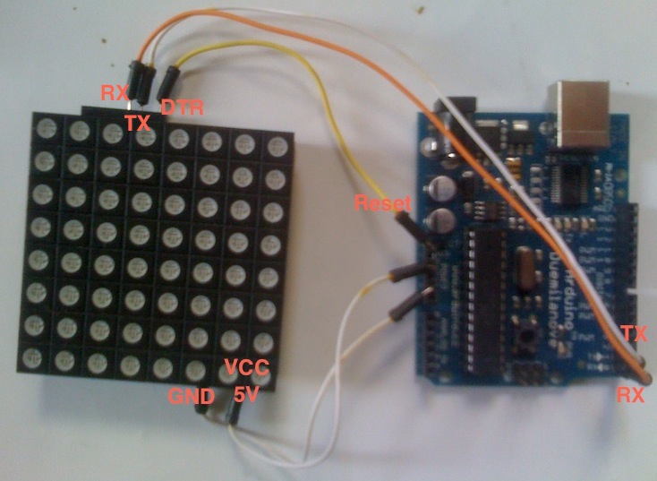
Step 3:
Open the rainbowduino firmware sketch, select the serial port and the correct board and upload the sketch.
In this case, even though I am using and Arduino Uno I select Atmega 168 As the board.
The rainbowduino should enter its default rainbow state if the upload was successful.
Step 4:
Add the Rainbowduino v3 firmware master folder to the Arduino libraries. This should containt WireCommnad.h and WireCommuncation.h
Controlling the RainbowDuino
Achieved through IC2 protocol.
A4 to SDA
A5 to SCL
RST to DTR
VCC to 5V
GND to GND

Reference LIbrary
http://code.google.com/p/rainbowduino-firmware/wiki/FirmwareFunctionsReference
Initialising the RainbowDuino
// variables for sending data
unsigned char RainbowCMD[20]; // buffer for storing the commands as they are send byte by byte
unsigned char State = 0; // determines send or receive command 0 for send
unsigned long timeout; // transfer timeout value
byte remoteAddr = 0x10; // bus address of rainbowduino
setup() {
Wire.begin();
RainbowCMD[0] = 'r';
sendCMD(0x10, CMD_SET_PAPER, 0, 0, 0);
}
void sendCommand() //wrapper
void sendWireCommand() // send across the I2C bus
void toByte() // int to byte convertor
Drawing Images
The device has two buffers that are swapped. You sends display message to a buffer and call the swap buffer method to display the new image. This allows multiple draw command to be send to construct the image and set the color ect before displaying it.
//sendCMD(0x10, CMD_CLEAR_PAPER);
sendCMD(0x10, CMD_SET_INK, 0xD, 0xF, 0x00);
sendCMD(0x10, CMD_DRAW_PIXEL, toByte(x), toByte(y));
sendCMD(0x10, CMD_SWAP_BUF);
Sunday, 18 September 2011
Mic Audio Sampling
Using the Audio sound sensor to try to capture audio data.
The Code:
Setup:
startTime = millis();
Main Loop
if(!end) {
sensorRead = analogRead(A0);
file.println(sensorRead); // write the read to the file
}
// stop the recording after 10 seconds
if (millis() > 10000) {
endTime = millis();
duration = endTime - startTime;
file.println(duration);
file.close(); //Close the file.
end=true;
Serial.print("done");
while(1);
}
Each sensor reading is written to the text file. This loop records makes note of the start and end time to calculate the length (for future designs when length will not be set at 10 secs). The duration is added as the final value.
Results
After running the output file through he wave convertor I ended up wit the following file. The recording is me saying "hello" into the mic over and over. The wave convertor calculates the sample rate at 3289sample/sec. I need to investigate other sensors and see if a raw write will allow faster sampling.
The Code:
Setup:
startTime = millis();
Main Loop
if(!end) {
sensorRead = analogRead(A0);
file.println(sensorRead); // write the read to the file
}
// stop the recording after 10 seconds
if (millis() > 10000) {
endTime = millis();
duration = endTime - startTime;
file.println(duration);
file.close(); //Close the file.
end=true;
Serial.print("done");
while(1);
}
Each sensor reading is written to the text file. This loop records makes note of the start and end time to calculate the length (for future designs when length will not be set at 10 secs). The duration is added as the final value.
Results
After running the output file through he wave convertor I ended up wit the following file. The recording is me saying "hello" into the mic over and over. The wave convertor calculates the sample rate at 3289sample/sec. I need to investigate other sensors and see if a raw write will allow faster sampling.
Java Wave Creator
After failing to create an audio header on the arduino I found a Java library that writes audio data to a wav file. This actually works out better as more of the processing is shifted off the arduino.
Java Wave File I/O
The
This class reads the data from a text file created by the Arduino. As this is 8 bit recording all values are between 0-255. I need to investigate if scaling will be required to normalise the sound.
Creating the Wave file:
Before creating the wave file the length and duration of the recording must be calculated.
This is achieved by opening the text file, couting each sample and storign the last value, as it is the duration in miliseconds.
This method creates a new wav file for writing to. It writes header information to the wav file. Once this method has been called and a
file : File output = new File(output.wav"); // specifies the output file
Again the data text file is opened however this time each value is added to the wav file
The last value is excluded as it is the length.
Java Wave File I/O
The
WavFile class takes care of all the file IO for reading and writing audio data to and from wave files. The WavFile class provides methods for accessing wav file data using different java primitive types, these are long, int and double. It is up to the user to choose the correct type for the given wav file's sample resolution.This class reads the data from a text file created by the Arduino. As this is 8 bit recording all values are between 0-255. I need to investigate if scaling will be required to normalise the sound.
Creating the Wave file:
Before creating the wave file the length and duration of the recording must be calculated.
This is achieved by opening the text file, couting each sample and storign the last value, as it is the duration in miliseconds.
BufferedReader br = new BufferedReader(new FileReader(fileName));
String strLine;
//Read File Line By Line
while ((strLine = br.readLine()) != null) {
numSamples++;
duration = Double.parseDouble(strLine)/1000;
}
numSamples--; // compstate for the legnth on the end
//Close the input stream
br.close();
Also, the sample rate must be calculated before preccding. sampleRate = (int) (numSamples / duration);
Now the wave file can be instantiated.
newWavFile(File file, int numChannels, long numFrames, int validBits, long sampleRate) throws IOException, WavFileExceptionThis method creates a new wav file for writing to. It writes header information to the wav file. Once this method has been called and a
WavFile instance retrieved, thewriteFrames methods can be used to write samples to the wav file.file : File output = new File(output.wav"); // specifies the output file
Again the data text file is opened however this time each value is added to the wav file
The last value is excluded as it is the length.
// Create a wav file with the name specified as the first argument
WavFile wavFile = WavFile.newWavFile(outfile, numChannels, numSamples, bitRate, sampleRate);
BufferedReader br = new BufferedReader(new FileReader(fileName));
String strLine;
//Read File Line By Line
int i = 0;
while (i <= numSamples) {
strLine = br.readLine();
i++;
//System.out.print(strLine);
int[] value = {Integer.parseInt(strLine)};
wavFile.writeFrames(value, 1);
}
//Close the input stream
br.close();
wavFile.close();
Subscribe to:
Posts (Atom)