Using a buffer to write sensor values to a SD card at 2000samples/sec+.
The time interval is 250um = 4000 samples/sec.
This works but produces alot of noise. Reading the Mic directly from A0.
Using SD Shield and SD FAT beta library (though the other one works) but code says must be newest version.
Define SD SS pin = 8 in the fastLogger sketch. Define the pins the SD library is ridiculous.
Works with the JAVA wav creator and reads hex as its faster.
Tuesday, 4 October 2011

Thursday, 29 September 2011
DrumHero Game
Concept:
Using the 8x8 RainbowDuino LED matrix and various vibration sensors and buttons to create a guitar hero style game for playing an electronic drumkit. This is a working example of several research areas including timers, interrupts, sensor readings, I2C bus
Mapping the LED Matrix:
To be able to manipulate the matrix it is represented in code by a 2D array containing on/off values (int 0 or 1)
int displayGrid[LEDs/2][LEDs]; // the LED matrix
initially this is initialised with all values as false. This creates a 4x8 matrix. We are dealing with 4 column as that is reasonable for a drumkit and allows each channel to occupy 2 LED's. This is much easier to view.
From here the Rainbow duino's buffer is written by reading each value of the array and colouring in the matching pixel.
void refreshDisplay() {
sendCMD(0x10, CMD_CLEAR_PAPER);
for(int x=0; x<LEDs/2; x++) {
for (int y=0; y<LEDs; y++) {
if (displayGrid[x][y] == 1) {
if (y==0) {
sendCMD(0x10, CMD_SET_INK, 0xF, 0x0, 0);
} else {
//Serial.print("on");
sendCMD(0x10, CMD_SET_INK, 0xD, 0xF, 0x00);
}
sendCMD(0x10, CMD_DRAW_PIXEL, toByte(x*2), toByte(y));
sendCMD(0x10, CMD_DRAW_PIXEL, toByte(x*2+1), toByte(y));
}
}
//sendCMD(0x10, CMD_CLEAR_PAPER);
}
sendCMD(0x10, CMD_SWAP_BUF);
}
Creating the Tempo
The game is controlled by an internal metronone that keeps tack of the beat. This is achieved through a hardware timer "TimeOne.h". Using a timer is the only way to accurately produce a tempo, using millis() would be inaccurate as other parts of the code could hold the program up.
Timer1.initialize(500000); // initialise timer1, and set a 1/2 second period
Once the timer is setup we attach an interrupt that calls a method every time the timer ticks.
Timer1.attachInterrupt(callback); // attaches callback() as a timer overflow interrupt
By doing this we ensure we catch every tick of the timer and therefore maintain a constant beat. This also allows fine grain control over tempo.
In the callback() method we increase the beatCount by one and let the program know that the counters needs to be moved. Callback method should be as simple as possible to not hold up other parts of the code.
void callback()
{
beatCount++;
moveCounters = true;
}
Controlling each Channel
For the moment each channel display dots at a certain freq., simulating a drum kit rhythm.
Each tick of the timer represents a
Semi quaver (or 16th note). = 1 timer tick
Quaver = 8th note = 2 timer ticks
Crotchet = 1/4 note = 4 timer ticks
Minum = 1/2 note = 8 timer ticks
Whole = 1 = 16 timer ticks
The main loop checks to see what the current beat count and checks to see if each channels note duration requires an action.
The counters for each channel are controlled by two methods. One that starts a pulse at the top LED of the column and another than scans each column and moves and pulses down 1 row. Every tick of the timer results in all counters being moved down a row. The frequency is controlled by starting the column at different times.
if (moveCounters) { // if the timer has ticked over
for (int x=0; x<channels; x++){ // for each channel
updateCol(x); // update the current counters
if (beatCount % delays[x] == 0) { //if a new counter is needed
startCol(x); // create a counter at the top of the col
}
}
refreshDisplay();
moveCounters = false; // reset flag for next timer tick
}
void updateCol(int col) {
for (int y=0; y<LEDs; y++) { // for each row in the col
if (displayGrid[col][y]) { // if this LED is on
displayGrid[col][y] = false; // turn it off
if (y>0) { // if this is not the bottom row
displayGrid[col][y-1] = true; // turn on the LED under
}
}
}
}
void startCol(int col) {
displayGrid[col][LEDs-1] = true; // turn on the top LED
}
With a few adjustments to the display method to do some colors you endup with the following...

Using the 8x8 RainbowDuino LED matrix and various vibration sensors and buttons to create a guitar hero style game for playing an electronic drumkit. This is a working example of several research areas including timers, interrupts, sensor readings, I2C bus
Mapping the LED Matrix:
To be able to manipulate the matrix it is represented in code by a 2D array containing on/off values (int 0 or 1)
int displayGrid[LEDs/2][LEDs]; // the LED matrix
initially this is initialised with all values as false. This creates a 4x8 matrix. We are dealing with 4 column as that is reasonable for a drumkit and allows each channel to occupy 2 LED's. This is much easier to view.
From here the Rainbow duino's buffer is written by reading each value of the array and colouring in the matching pixel.
void refreshDisplay() {
sendCMD(0x10, CMD_CLEAR_PAPER);
for(int x=0; x<LEDs/2; x++) {
for (int y=0; y<LEDs; y++) {
if (displayGrid[x][y] == 1) {
if (y==0) {
sendCMD(0x10, CMD_SET_INK, 0xF, 0x0, 0);
} else {
//Serial.print("on");
sendCMD(0x10, CMD_SET_INK, 0xD, 0xF, 0x00);
}
sendCMD(0x10, CMD_DRAW_PIXEL, toByte(x*2), toByte(y));
sendCMD(0x10, CMD_DRAW_PIXEL, toByte(x*2+1), toByte(y));
}
}
//sendCMD(0x10, CMD_CLEAR_PAPER);
}
sendCMD(0x10, CMD_SWAP_BUF);
}
Creating the Tempo
The game is controlled by an internal metronone that keeps tack of the beat. This is achieved through a hardware timer "TimeOne.h". Using a timer is the only way to accurately produce a tempo, using millis() would be inaccurate as other parts of the code could hold the program up.
Timer1.initialize(500000); // initialise timer1, and set a 1/2 second period
Once the timer is setup we attach an interrupt that calls a method every time the timer ticks.
Timer1.attachInterrupt(callback); // attaches callback() as a timer overflow interrupt
By doing this we ensure we catch every tick of the timer and therefore maintain a constant beat. This also allows fine grain control over tempo.
In the callback() method we increase the beatCount by one and let the program know that the counters needs to be moved. Callback method should be as simple as possible to not hold up other parts of the code.
void callback()
{
beatCount++;
moveCounters = true;
}
Controlling each Channel
For the moment each channel display dots at a certain freq., simulating a drum kit rhythm.
Each tick of the timer represents a
Semi quaver (or 16th note). = 1 timer tick
Quaver = 8th note = 2 timer ticks
Crotchet = 1/4 note = 4 timer ticks
Minum = 1/2 note = 8 timer ticks
Whole = 1 = 16 timer ticks
The main loop checks to see what the current beat count and checks to see if each channels note duration requires an action.
The counters for each channel are controlled by two methods. One that starts a pulse at the top LED of the column and another than scans each column and moves and pulses down 1 row. Every tick of the timer results in all counters being moved down a row. The frequency is controlled by starting the column at different times.
if (moveCounters) { // if the timer has ticked over
for (int x=0; x<channels; x++){ // for each channel
updateCol(x); // update the current counters
if (beatCount % delays[x] == 0) { //if a new counter is needed
startCol(x); // create a counter at the top of the col
}
}
refreshDisplay();
moveCounters = false; // reset flag for next timer tick
}
void updateCol(int col) {
for (int y=0; y<LEDs; y++) { // for each row in the col
if (displayGrid[col][y]) { // if this LED is on
displayGrid[col][y] = false; // turn it off
if (y>0) { // if this is not the bottom row
displayGrid[col][y-1] = true; // turn on the LED under
}
}
}
}
void startCol(int col) {
displayGrid[col][LEDs-1] = true; // turn on the top LED
}
With a few adjustments to the display method to do some colors you endup with the following...

Mic Based Interrupts
Problem:
We need to be able to wake the Arduino when the koala starts calling. The initial test is a volume test. We want the Arduino to wake up when the mic registers a load noise.
To wake the Arduino from sleep an interrupt must be generated and sent to pin 2 or 3.
Although the attach interrupt method allows various parameters to be set for the interrupt (high, low, faling etc) in any mode except "Idle" only Low can be used.
This poses a problem as we need to generate a low signal when the mic reading reaches a certain threshold. Also, as LOW is defined as 0-2V the ambient reading from the mic is actually a LOW signal and it continually wakes the Arduino. Pulling the PIN high with a pull-up resistor pulls it high, but only while nothing is connected. Once the sensor is plugged back in the pin reads normal values. Though in some cases (sound sensor) the pull-up resistor affected the reading.
Solution:
Using and operational pre-amp to set a threshold voltage and generate a low signal when the signal crosses the threshold. An Operational Amplifier (op-amp) is designed to amplify the difference between the V+ and V- input pins. Since the amplifier has very high gain, in this configuration its output is either fully on, or fully off, depending on whether the input (in this case on V-) is greater than, or less than, the reference voltage we put on V+. I am using the LM358

LM358
PIN1 to Arduino interrupt pin. This output will snap low when the input exceeds the reference voltage.
PIN 2 to Mic Signal Output. This is the signal we will monitor
PIN3 to POT signal Out. The pot provides an adjustable reference voltage.
PIN 4 to ground
PIN 5, 6, 7 provide a second input
PIN 8 5V Power supply
Both Mic and Pot are connected through pull-up resistors. Once a threshold V has been calculated we might replace the pot with resistors and hard wire it in.
We need to be able to wake the Arduino when the koala starts calling. The initial test is a volume test. We want the Arduino to wake up when the mic registers a load noise.
To wake the Arduino from sleep an interrupt must be generated and sent to pin 2 or 3.
Although the attach interrupt method allows various parameters to be set for the interrupt (high, low, faling etc) in any mode except "Idle" only Low can be used.
This poses a problem as we need to generate a low signal when the mic reading reaches a certain threshold. Also, as LOW is defined as 0-2V the ambient reading from the mic is actually a LOW signal and it continually wakes the Arduino. Pulling the PIN high with a pull-up resistor pulls it high, but only while nothing is connected. Once the sensor is plugged back in the pin reads normal values. Though in some cases (sound sensor) the pull-up resistor affected the reading.
Solution:
Using and operational pre-amp to set a threshold voltage and generate a low signal when the signal crosses the threshold. An Operational Amplifier (op-amp) is designed to amplify the difference between the V+ and V- input pins. Since the amplifier has very high gain, in this configuration its output is either fully on, or fully off, depending on whether the input (in this case on V-) is greater than, or less than, the reference voltage we put on V+. I am using the LM358

PIN1 to Arduino interrupt pin. This output will snap low when the input exceeds the reference voltage.
PIN 2 to Mic Signal Output. This is the signal we will monitor
PIN3 to POT signal Out. The pot provides an adjustable reference voltage.
PIN 4 to ground
PIN 5, 6, 7 provide a second input
PIN 8 5V Power supply
Both Mic and Pot are connected through pull-up resistors. Once a threshold V has been calculated we might replace the pot with resistors and hard wire it in.
RainbowDuino
The Rainbowduino board is an Arduino compatible controller board with professional LED driving capacity. It will drive an 8x8 RGB Led Matrix.
Tech Specs:
- No external circuit required, plug and shine!
- 24 constant current channels of 120mA each
- 8 super source driver channel of 500mA each
- Wide output voltage adaption from 6.5V-12VDC (runs off Arduino 5V)
- Dedicated GPIO and ADC
- Hardware UART and I2C communication
To get the Rainbowduino up and running some firmware needs to be uploaded to the device.
There are several versions available however the simplest seems to be "RainbowDuino Firmware Version 3"
http://code.google.com/p/rainbowduino-firmware/
Uploading the Firmware:
There are several ways to go about doing this - via Arduino, via Xbee USB. Via Arduino seems the simplest.
Step 1:
Make sure that your Arduino has no software running. To erase any code, flash the processor with the following void code:
void setup(){
}
void loop(){
}
Step 2:
Connections:
Flashing the firmware requires the serial connection so connect:
Rainbowduino -- > Arduino
RX 0/RX
TX 1/TX
DTR Reset
VCC 5V
GND GND
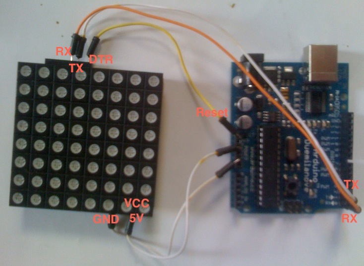
Step 3:
Open the rainbowduino firmware sketch, select the serial port and the correct board and upload the sketch.
In this case, even though I am using and Arduino Uno I select Atmega 168 As the board.
The rainbowduino should enter its default rainbow state if the upload was successful.
Step 4:
Add the Rainbowduino v3 firmware master folder to the Arduino libraries. This should containt WireCommnad.h and WireCommuncation.h
Controlling the RainbowDuino
Achieved through IC2 protocol.
A4 to SDA
A5 to SCL
RST to DTR
VCC to 5V
GND to GND

Reference LIbrary
http://code.google.com/p/rainbowduino-firmware/wiki/FirmwareFunctionsReference
Initialising the RainbowDuino
// variables for sending data
unsigned char RainbowCMD[20]; // buffer for storing the commands as they are send byte by byte
unsigned char State = 0; // determines send or receive command 0 for send
unsigned long timeout; // transfer timeout value
byte remoteAddr = 0x10; // bus address of rainbowduino
setup() {
Wire.begin();
RainbowCMD[0] = 'r';
sendCMD(0x10, CMD_SET_PAPER, 0, 0, 0);
}
void sendCommand() //wrapper
void sendWireCommand() // send across the I2C bus
void toByte() // int to byte convertor
Drawing Images
The device has two buffers that are swapped. You sends display message to a buffer and call the swap buffer method to display the new image. This allows multiple draw command to be send to construct the image and set the color ect before displaying it.
//sendCMD(0x10, CMD_CLEAR_PAPER);
sendCMD(0x10, CMD_SET_INK, 0xD, 0xF, 0x00);
sendCMD(0x10, CMD_DRAW_PIXEL, toByte(x), toByte(y));
sendCMD(0x10, CMD_SWAP_BUF);
Sunday, 18 September 2011
Mic Audio Sampling
Using the Audio sound sensor to try to capture audio data.
The Code:
Setup:
startTime = millis();
Main Loop
if(!end) {
sensorRead = analogRead(A0);
file.println(sensorRead); // write the read to the file
}
// stop the recording after 10 seconds
if (millis() > 10000) {
endTime = millis();
duration = endTime - startTime;
file.println(duration);
file.close(); //Close the file.
end=true;
Serial.print("done");
while(1);
}
Each sensor reading is written to the text file. This loop records makes note of the start and end time to calculate the length (for future designs when length will not be set at 10 secs). The duration is added as the final value.
Results
After running the output file through he wave convertor I ended up wit the following file. The recording is me saying "hello" into the mic over and over. The wave convertor calculates the sample rate at 3289sample/sec. I need to investigate other sensors and see if a raw write will allow faster sampling.
The Code:
Setup:
startTime = millis();
Main Loop
if(!end) {
sensorRead = analogRead(A0);
file.println(sensorRead); // write the read to the file
}
// stop the recording after 10 seconds
if (millis() > 10000) {
endTime = millis();
duration = endTime - startTime;
file.println(duration);
file.close(); //Close the file.
end=true;
Serial.print("done");
while(1);
}
Each sensor reading is written to the text file. This loop records makes note of the start and end time to calculate the length (for future designs when length will not be set at 10 secs). The duration is added as the final value.
Results
After running the output file through he wave convertor I ended up wit the following file. The recording is me saying "hello" into the mic over and over. The wave convertor calculates the sample rate at 3289sample/sec. I need to investigate other sensors and see if a raw write will allow faster sampling.
Java Wave Creator
After failing to create an audio header on the arduino I found a Java library that writes audio data to a wav file. This actually works out better as more of the processing is shifted off the arduino.
Java Wave File I/O
The
This class reads the data from a text file created by the Arduino. As this is 8 bit recording all values are between 0-255. I need to investigate if scaling will be required to normalise the sound.
Creating the Wave file:
Before creating the wave file the length and duration of the recording must be calculated.
This is achieved by opening the text file, couting each sample and storign the last value, as it is the duration in miliseconds.
This method creates a new wav file for writing to. It writes header information to the wav file. Once this method has been called and a
file : File output = new File(output.wav"); // specifies the output file
Again the data text file is opened however this time each value is added to the wav file
The last value is excluded as it is the length.
Java Wave File I/O
The
WavFile class takes care of all the file IO for reading and writing audio data to and from wave files. The WavFile class provides methods for accessing wav file data using different java primitive types, these are long, int and double. It is up to the user to choose the correct type for the given wav file's sample resolution.This class reads the data from a text file created by the Arduino. As this is 8 bit recording all values are between 0-255. I need to investigate if scaling will be required to normalise the sound.
Creating the Wave file:
Before creating the wave file the length and duration of the recording must be calculated.
This is achieved by opening the text file, couting each sample and storign the last value, as it is the duration in miliseconds.
BufferedReader br = new BufferedReader(new FileReader(fileName));
String strLine;
//Read File Line By Line
while ((strLine = br.readLine()) != null) {
numSamples++;
duration = Double.parseDouble(strLine)/1000;
}
numSamples--; // compstate for the legnth on the end
//Close the input stream
br.close();
Also, the sample rate must be calculated before preccding. sampleRate = (int) (numSamples / duration);
Now the wave file can be instantiated.
newWavFile(File file, int numChannels, long numFrames, int validBits, long sampleRate) throws IOException, WavFileExceptionThis method creates a new wav file for writing to. It writes header information to the wav file. Once this method has been called and a
WavFile instance retrieved, thewriteFrames methods can be used to write samples to the wav file.file : File output = new File(output.wav"); // specifies the output file
Again the data text file is opened however this time each value is added to the wav file
The last value is excluded as it is the length.
// Create a wav file with the name specified as the first argument
WavFile wavFile = WavFile.newWavFile(outfile, numChannels, numSamples, bitRate, sampleRate);
BufferedReader br = new BufferedReader(new FileReader(fileName));
String strLine;
//Read File Line By Line
int i = 0;
while (i <= numSamples) {
strLine = br.readLine();
i++;
//System.out.print(strLine);
int[] value = {Integer.parseInt(strLine)};
wavFile.writeFrames(value, 1);
}
//Close the input stream
br.close();
wavFile.close();
Tuesday, 6 September 2011
Midi Motion Sensors
Aim: Using the IR sensor to create a thermion like instrument
Connections:
To create the midi interface connect the Arduino to a 5pin Din plug as shown. A 220ohm resistor is needed to lower the 5V power.

Code:
From my tests I know the IR sensor reads values from approx. 0 - 600. To create the simple instrument i mapped each of these sensor readings to a MIDI note value (0-127).
The Midi Library provides a simple way to send midi signals.
Once MIDI.begin() is send the serial port is used for MIDI and cannot print message to the serial reader. Midi uses a customer Baud rate (31250).
Results:
Connections:
To create the midi interface connect the Arduino to a 5pin Din plug as shown. A 220ohm resistor is needed to lower the 5V power.
Code:
From my tests I know the IR sensor reads values from approx. 0 - 600. To create the simple instrument i mapped each of these sensor readings to a MIDI note value (0-127).
The Midi Library provides a simple way to send midi signals.
| void | begin (const byte inChannel=1) |
| Call the begin method in the setup() function of the Arduino. | |
| void | sendNoteOn (byte NoteNumber, byte Velocity, byte Channel) |
| Send a Note On message. | |
| void | sendNoteOff (byte NoteNumber, byte Velocity, byte Channel) |
| Send a Note Off message (a real Note Off, not a Note On with null velocity) |
| void | sendProgramChange (byte ProgramNumber, byte Channel) |
| Send a Program Change message. |
Once MIDI.begin() is send the serial port is used for MIDI and cannot print message to the serial reader. Midi uses a customer Baud rate (31250).
Results:
Monday, 5 September 2011
Sensor Capabilities
Potentiometer
Read Protocol: Analogue
Values: 0-1023
Voltage: 5V
Mic
Read Protocol: Unknown - needs further investigation
Values: unknown
Voltage: 2.2V - 7V
Ultrasonic Distance Sensor
Read Protocol: Digital
Values: 0-1
Voltage: 5V
This sensor uses a ping operation to calculate distance. The connected pin is first set to out and a short burst is emitted. The pin is then switch back to input to read the reflected signal.
To connect this to the shield ensure that the plug is connect slip side up. See the picture below
IR Distance Sensor
Read Protocol: Analogue
Values: 0-600
Voltage: 5V
Originally the connector cable was wired incorrectly so i had to swap to signal pin around. Of note the sensor reaches it max value about 10cm away from the LEDs. Once you move close than this the value decreases till about 500 when your hand is over the sensor.
Read Protocol: Analogue
Values: 0-1023
Voltage: 5V
Mic
Read Protocol: Unknown - needs further investigation
Values: unknown
Voltage: 2.2V - 7V
Ultrasonic Distance Sensor
Read Protocol: Digital
Values: 0-1
Voltage: 5V
This sensor uses a ping operation to calculate distance. The connected pin is first set to out and a short burst is emitted. The pin is then switch back to input to read the reflected signal.
To connect this to the shield ensure that the plug is connect slip side up. See the picture below
IR Distance Sensor
Read Protocol: Analogue
Values: 0-600
Voltage: 5V
Originally the connector cable was wired incorrectly so i had to swap to signal pin around. Of note the sensor reaches it max value about 10cm away from the LEDs. Once you move close than this the value decreases till about 500 when your hand is over the sensor.
Temperature Sensor
Read Protocol: Analogue
Values: 0-?
Voltage: 5V ok
Room temp: about 512
Upon touch the temp instantly rises to about 540 and steadily increases.
Read Protocol: Analogue
Values: 0-?
Voltage: 5V ok
Room temp: about 512
Upon touch the temp instantly rises to about 540 and steadily increases.
ADKeyboard Module
Read Protocol: Analogue
Values: 50, 200, 400, 600, 800 (serial readings more like 0, 143, 329, 504, 742)
Voltage: 5V
Read Protocol: Analogue
Values: 50, 200, 400, 600, 800 (serial readings more like 0, 143, 329, 504, 742)
Voltage: 5V
PS2 Control Module
Read Protocol: Analogue
Values: 0-1023 x 2 plus button
Voltage: 5V
Although this unit has two ground pins both x and y values could be read connecting either. Still need to investigate the button.
Read Protocol: Analogue
Values: 0-1023 x 2 plus button
Voltage: 5V
Although this unit has two ground pins both x and y values could be read connecting either. Still need to investigate the button.
Thursday, 25 August 2011
Booting into recording Mode
Loading the VS1053 into encoding mode using the PCM encoder.
Although it is not on the datasheet, I think it would be necessary to set the mode register.
The music shield does a Software Reset with the following values...
Mp3WriteRegister (SPI_MODE, 0x08, 0x04); /* Newmode, Reset, No L1-2 */
delay(1);
while (!MP3_DREQ) /* wait for startup */
0x0804 is 0000 1000 0000 0100 (ie the first 0 is written to register bit 15)
SDI-NEWMODE(11) - ON
Soft Reset(2)
It also writes the clock doubler and misc audio data. I dont think this is necessary though as its not mentioned in the data sheet at all. This makes me think that resetting clears the all the registers except the mode register (reset bit is auto cleared). I need to check that Mode(bit 11) stays set ensure SDI NEW mode is entered. Unreliability of serial prints makes it difficult to check. Probably wouldn't hurt to send 0000 1000 0000 0000 0x0800 to be sure.
/* Set clock register, doubler etc. */
Mp3WriteRegisterWithDelay(SPI_CLOCKF, 0xB8, 0x00);
while (!MP3_DREQ);
Mp3WriteRegister(SPI_AUDATA, 0xAC,0x45);
while (!MP3_DREQ);
Steps From the DataSheet
Although it is not on the datasheet, I think it would be necessary to set the mode register.
The music shield does a Software Reset with the following values...
Mp3WriteRegister (SPI_MODE, 0x08, 0x04); /* Newmode, Reset, No L1-2 */
delay(1);
while (!MP3_DREQ) /* wait for startup */
0x0804 is 0000 1000 0000 0100 (ie the first 0 is written to register bit 15)
SDI-NEWMODE(11) - ON
Soft Reset(2)
It also writes the clock doubler and misc audio data. I dont think this is necessary though as its not mentioned in the data sheet at all. This makes me think that resetting clears the all the registers except the mode register (reset bit is auto cleared). I need to check that Mode(bit 11) stays set ensure SDI NEW mode is entered. Unreliability of serial prints makes it difficult to check. Probably wouldn't hurt to send 0000 1000 0000 0000 0x0800 to be sure.
/* Set clock register, doubler etc. */
Mp3WriteRegisterWithDelay(SPI_CLOCKF, 0xB8, 0x00);
while (!MP3_DREQ);
Mp3WriteRegister(SPI_AUDATA, 0xAC,0x45);
while (!MP3_DREQ);
Steps From the DataSheet
- Set the VS1053b clock to the highest value just below 55.3 by writing 0xC000 to register SCI_CLOCKF (3)
Write1053Sci(SCIR_CLOCKF, 0xC0, 0x00);
- Set SCI_BASS (2) to 0.
- Reset VS1053b by setting bit SM_RESET (2) to 1 in register SCI_MODE (0). At the same time, clear bit SM_ADPCM (12) to 0. Remember that resetting takes time, so don’t do any firther register writes before the DREQ pin has risen.This step seems unneccessary as reseting at this point would remove the previous two steps. In the music shield example (Alsso OGG) this step is removed and is also not mention in the PCM recording instructions.
Write1053Sci(SCIR_MODE, 0x08, 0x04); // 0000 1000 0000 0000 0100
while(!digitalRead(MP3_DREQ)) ;
- Disable all interrupts except the SCI interrupts.In the music shield example the AIADDR register is also cleared. This is also mentioned in the PCM recording datasheet.
Mp3WriteRegister(SPI_AIADDR, 0x00,0x00);).
Mp3WriteRegister(SPI_WRAMADDR, 0xC0,0x1A);
Mp3WriteRegister(SPI_WRAM, 0x00,0x02); - Load the plugin profile you intend to run (Chapter 4). Note that you will have to redo this each time you want to activate recording.This poses a problem as you cant store a file on the Arduino. For the moment I will be using the .plg low quality voice profile. To save hassle I think i will try copying the vector variable to my sketch and reading it that way, avoiding the need for an SD card. The Ogg vorbis encoder will not fit on the arduino uno however the PCM profile is much smaller.
- Write1053Sci(SCIR_MODE, 0x18, 0x00); //0001 1000 0000 0000 for new mode For Line:Set bit SM_ADPCM (12) in register SCI_MODE (0) to 1.For Mic input
Write1053Sci(SCIR_MODE, 0x58, 0x00); //0101 1000 0000 0000 for new mode
- Set recording level control registers SCI_AICTRL1 (13) and SCI_AICTRL2 (14). Typical good values for conservative AGC are 0 and 4096, respectively.
/* If 0, use AGC */
Write1053Sci(SCIR_AICTRL1, 0x00, 0x00);
/* set to 4096 */
Write1053Sci(SCIR_AICTRL2, 0x10,0x00); // 0001 0000 0000 0000 = 4096 (decimal)
- If you want to use a VU meter, write 0x8000 to SCI_AICTRL0 (12) if using a mono profile or 0x8080 is using a stereo profile.No Need:Write1053Sci(SCIR_AICTRL0, 0x00, 0x00);
- Set a proper value ( 0) to SCI_AICTRL3 (15).Write1053Sci(SCIR_AICTRL3, 0x00, 0x00)
- If you use a profile that support Vox, set Vox registers. For details, see Chapter 2.5.
Not gonna look into this yet
- Activate the encoder by writing 0x34 to register SCI_AIADDR (10).
Mp3WriteRegister(SPI_AIADDR, 0x00,0x34); - Wait until DREQ pin is high before reading any data.
Wednesday, 24 August 2011
VS1053 SPI Specs
Loading the VS1053 and starting the Ogg Vorbis encoder requires communicating with the board via SDI interface.
SDI Connections:
Connected via 4 pins on VS1053
SPI VS1053 Commands
Read:
unsigned short resultvalue = 0;
unsigned char h = 0;
unsigned char l = 0;
Mp3DeselectData(); // BYSNC High
Mp3SelectControl();// CS low
SPI.transfer(VS_READ_COMMAND); //send read command
SPI.transfer(addressbyte); //send register address
//be careful: when read 0xff,dump it,and read agin
//while((h = SPIGetChar())== 0xff);
h = SPIGetChar();
//while((l = VsReadByte())== 0xff);
l = SPIGetChar();
resultvalue = ((h << 8) | l);
Mp3DeselectControl(); // CS High
return resultvalue;
unsigned char SPIGetChar(){
unsigned char returned = SPI.transfer(0xFF); // transfer dummy data
return returned; /* Return the received byte */
}
Write:
First, XCS line is pulled low to select the device.
Then the WRITE opcode (0x2) is transmitted via the SI line
Then followed by an 8-bit word address.
Mp3DeselectData(); // BYSNC High
Mp3SelectControl(); //CS Low
//SPIPutCharWithoutWaiting(VS_WRITE_COMMAND);
SPI.transfer(VS_WRITE_COMMAND);
//delay(1);
SPI.transfer((addressbyte));
SPI.transfer((highbyte));
SPI.transfer((lowbyte));
SPIWait();
Mp3DeselectControl(); //CS Low
This follows the sequnce from the music shield code. In my interpretation of the datasheet CS should be driven low after the words have been transfered as oppose to after DREQ has returned high (signally update is complete)
The issues i faced is controlling the BYSNC Pin. From what I can tell I am using SDI new mode, in which the BSYNC signal is automatically generated. However, all the code examples write a value to this pin before a read or write command. The Music Shield example pulls the pin high as stated in the datasheet, however other examples pull it low.
VS1053 SDI Modes
Two modes available (native and compatibility mode) controlled by SM_SDINEW(11) in MODE(0) register. The modes vary in the way they achieve bit sync.
In native mode:
SM-SDINEW is set to 1 and bit sync is achieved by internally by XDCS. Page 19 on vs1053 datasheet indicates that this is just using the select pin.
In compatibility mode:
the BSYNC pin is used. BYSNC must be high on the first sample and if left high at the end on the first byte (8 bits) transfer, will cause the receiver to stay active and receive the next byte. Only 1 byte can be transfered at a time. This explains why all the register write example code take 2 paramaters. Each register entry must be sent as two 8-bit words.
SDI Connections:
Connected via 4 pins on VS1053
- MOSI – Master-out, Slave-in. This line carries data from our Arduino to the SPI-controlled device(s);
- MISO – Master-in, Slave out. This line carries data from the SPI-controlled device(s) back to the Arduino;
- SS – Slave-select. This line tells the device on the bus we wish to communicate with it. Each SPI device needs a unique SS line back to the Arduino. This line is LOW when communicating over the bus and high when finished.
- SCK – Serial clock.
VS1053 to Arduino Connections:
- SS – digital 9 (OUTPUT). You can use other digital pins, but 10 is generally the default as it is next to the other SPI pins. 10 is reserved for the MicroSD library so i will use 9
- MOSI – digital 11 - doesn't need to be set
- MISO – digital 12 - doesn't need to be set
- SCK – digital 13 doesn't need to be set
Also Need
- (BSYNC if needed... see modes) - any pin (OUTPUT) - using 2
- DREQ - any pin (INPUT) - using 3
The pins on the Arduino are set. Apparently those digital pins are optimised for SDI and cant be changed.
SPI Arduino Commands
Begin() - wake up the bus
end() - shut down the bus
setBitOrder() - msb Of lsb
setClockDivider()
setDataMode() - using mode0 for this application.
transfer() - transfer the byte, also returns the register value if a read command is used. In this case pass 0xff (all 1's)
Begin() - wake up the bus
end() - shut down the bus
setBitOrder() - msb Of lsb
setClockDivider()
setDataMode() - using mode0 for this application.
transfer() - transfer the byte, also returns the register value if a read command is used. In this case pass 0xff (all 1's)
SPI VS1053 Commands
Read:
First, XCS line is pulled low to select the device.
Then the READ opcode (0x3) is transmitted via the SI line
Then followed by an 8-bit word address. After the address has been read in, any further data on SI is ignored by the chip. The 16-bit data corresponding to the received address will be shifted out onto the SO line.
XCS should be driven high after data has been shifted out.
DREQ is driven low for a short while when in a read operation by the chip. This is a very short time and doesn’t require special user attention.
Then the READ opcode (0x3) is transmitted via the SI line
Then followed by an 8-bit word address. After the address has been read in, any further data on SI is ignored by the chip. The 16-bit data corresponding to the received address will be shifted out onto the SO line.
XCS should be driven high after data has been shifted out.
DREQ is driven low for a short while when in a read operation by the chip. This is a very short time and doesn’t require special user attention.
unsigned short resultvalue = 0;
unsigned char h = 0;
unsigned char l = 0;
Mp3DeselectData(); // BYSNC High
Mp3SelectControl();// CS low
SPI.transfer(VS_READ_COMMAND); //send read command
SPI.transfer(addressbyte); //send register address
//be careful: when read 0xff,dump it,and read agin
//while((h = SPIGetChar())== 0xff);
h = SPIGetChar();
//while((l = VsReadByte())== 0xff);
l = SPIGetChar();
resultvalue = ((h << 8) | l);
Mp3DeselectControl(); // CS High
return resultvalue;
unsigned char SPIGetChar(){
unsigned char returned = SPI.transfer(0xFF); // transfer dummy data
return returned; /* Return the received byte */
}
Write:
First, XCS line is pulled low to select the device.
Then the WRITE opcode (0x2) is transmitted via the SI line
Then followed by an 8-bit word address.
After the word has been shifted in and the last clock has been sent, XCS should be pulled high to end the WRITE sequence.
After the last bit has been sent, DREQ is driven low for the duration of the register update. Wait for DREQ to go high before performing another write.Mp3DeselectData(); // BYSNC High
Mp3SelectControl(); //CS Low
//SPIPutCharWithoutWaiting(VS_WRITE_COMMAND);
SPI.transfer(VS_WRITE_COMMAND);
//delay(1);
SPI.transfer((addressbyte));
SPI.transfer((highbyte));
SPI.transfer((lowbyte));
SPIWait();
Mp3DeselectControl(); //CS Low
This follows the sequnce from the music shield code. In my interpretation of the datasheet CS should be driven low after the words have been transfered as oppose to after DREQ has returned high (signally update is complete)
The issues i faced is controlling the BYSNC Pin. From what I can tell I am using SDI new mode, in which the BSYNC signal is automatically generated. However, all the code examples write a value to this pin before a read or write command. The Music Shield example pulls the pin high as stated in the datasheet, however other examples pull it low.
VS1053 SDI Modes
Two modes available (native and compatibility mode) controlled by SM_SDINEW(11) in MODE(0) register. The modes vary in the way they achieve bit sync.
In native mode:
SM-SDINEW is set to 1 and bit sync is achieved by internally by XDCS. Page 19 on vs1053 datasheet indicates that this is just using the select pin.
In VS1002 native modes (SM NEWMODE is 1), byte synchronisation is achieved by XDCS. The state of XDCS may not change while a data byte transfer is in progress. To always maintain data synchronisation even if there may be glitches in the boards using VS1053b, it is recommended to turn XDCS every now and then, for instance once after every disk data block, just to make sure the host and VS1053b are in sync.
If SM SDISHARE is 1, the XDCS signal is internally generated by inverting the XCS input.
In compatibility mode:
the BSYNC pin is used. BYSNC must be high on the first sample and if left high at the end on the first byte (8 bits) transfer, will cause the receiver to stay active and receive the next byte. Only 1 byte can be transfered at a time. This explains why all the register write example code take 2 paramaters. Each register entry must be sent as two 8-bit words.
When VS1053b is running in VS1001 compatibility mode, a BSYNC signal must be generated to ensure correct bit-alignment of the input bitstream. The first DCLK sampling edge (rising or falling, depending on selected polarity), during which the BSYNC is high, marks the first bit of a byte (LSB, if LSB-first order is used, MSB, if MSB-first order is used). If BSYNC is ’1’ when the last bit is received, the receiver stays active and next 8 bits are also received.
Tuesday, 9 August 2011
Generating Midi Signals
Using the Arduino to send various midi signals to the SV10XX board.
Chanel Setup:
Before sending the channel must be configured. I hage not tried without this code to see if there is a default.
Set Volume:
talkMIDI(0xB0, 0x07, 120); //0xB0 is channel message, set channel volume to near max (127)
Set Midi Bank:
talkMIDI(0xB0, 0, 0x00); //Default bank GM1
Set Instrument:
talkMIDI(0xC0, instrument, 0); //Set instrument number. 0xC0 is a 1 data byte command
It seems that in each of the commands changing the integer after the Upper care letter selects different channels, up to a max a 16.
NoteOn()/NoteOff()
Once this is done the noteOn() or noteOff() methods can be used with the parameters:
//Note on channel 1 (0x90), some note value (note), middle velocity (0x45):
noteOn(0, note, 60);
It is worthwhile nothing that some instruments dont require a note off. Drums for instance only last a set duration however wind instruments or synth will play until the noteOff is sent. Multiple noteOn message can be sent at once.
It is possible to change the instrument by sending multiple "Set Instrument" instructions however trying to working out which not to turn off can be difficult. The instrument doesn't not need to be set for the note off, the note value must match up though.
For multiple instruments creating different channels and setting an instrument to each channel seemed to be a better solution.
Using the percussion instruments requires accessing a different midi bank
talkMIDI(0xB0, 0, 0x78); //Bank select: drums
talkMIDI(0xC0, 5, 0); //Set instrument number
noteOn(0, 36, 60); //Play note on channel 1 (0x90), some note value (note), middle velocity (60):
Chanel Setup:
Before sending the channel must be configured. I hage not tried without this code to see if there is a default.
Set Volume:
talkMIDI(0xB0, 0x07, 120); //0xB0 is channel message, set channel volume to near max (127)
Set Midi Bank:
talkMIDI(0xB0, 0, 0x00); //Default bank GM1
Set Instrument:
talkMIDI(0xC0, instrument, 0); //Set instrument number. 0xC0 is a 1 data byte command
It seems that in each of the commands changing the integer after the Upper care letter selects different channels, up to a max a 16.
NoteOn()/NoteOff()
Once this is done the noteOn() or noteOff() methods can be used with the parameters:
//Note on channel 1 (0x90), some note value (note), middle velocity (0x45):
noteOn(0, note, 60);
It is worthwhile nothing that some instruments dont require a note off. Drums for instance only last a set duration however wind instruments or synth will play until the noteOff is sent. Multiple noteOn message can be sent at once.
It is possible to change the instrument by sending multiple "Set Instrument" instructions however trying to working out which not to turn off can be difficult. The instrument doesn't not need to be set for the note off, the note value must match up though.
For multiple instruments creating different channels and setting an instrument to each channel seemed to be a better solution.
Using the percussion instruments requires accessing a different midi bank
talkMIDI(0xB0, 0, 0x78); //Bank select: drums
talkMIDI(0xC0, 5, 0); //Set instrument number
noteOn(0, 36, 60); //Play note on channel 1 (0x90), some note value (note), middle velocity (60):
Subscribe to:
Posts (Atom)