The Rainbowduino board is an Arduino compatible controller board with professional LED driving capacity. It will drive an 8x8 RGB Led Matrix.
Tech Specs:
- No external circuit required, plug and shine!
- 24 constant current channels of 120mA each
- 8 super source driver channel of 500mA each
- Wide output voltage adaption from 6.5V-12VDC (runs off Arduino 5V)
- Dedicated GPIO and ADC
- Hardware UART and I2C communication
To get the Rainbowduino up and running some firmware needs to be uploaded to the device.
There are several versions available however the simplest seems to be "RainbowDuino Firmware Version 3"
http://code.google.com/p/rainbowduino-firmware/
Uploading the Firmware:
There are several ways to go about doing this - via Arduino, via Xbee USB. Via Arduino seems the simplest.
Step 1:
Make sure that your Arduino has no software running. To erase any code, flash the processor with the following void code:
void setup(){
}
void loop(){
}
Step 2:
Connections:
Flashing the firmware requires the serial connection so connect:
Rainbowduino -- > Arduino
RX 0/RX
TX 1/TX
DTR Reset
VCC 5V
GND GND
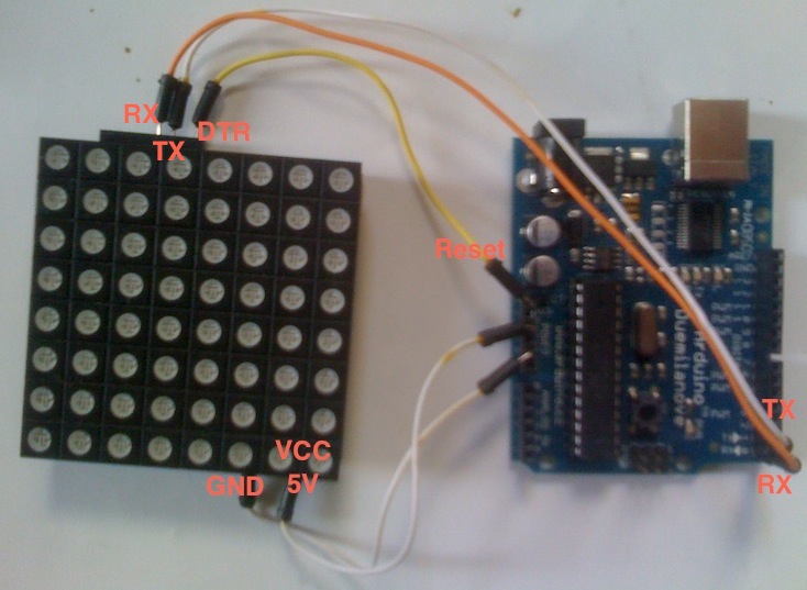
Step 3:
Open the rainbowduino firmware sketch, select the serial port and the correct board and upload the sketch.
In this case, even though I am using and Arduino Uno I select Atmega 168 As the board.
The rainbowduino should enter its default rainbow state if the upload was successful.
Step 4:
Add the Rainbowduino v3 firmware master folder to the Arduino libraries. This should containt WireCommnad.h and WireCommuncation.h
Controlling the RainbowDuino
Achieved through IC2 protocol.
A4 to SDA
A5 to SCL
RST to DTR
VCC to 5V
GND to GND

Reference LIbrary
http://code.google.com/p/rainbowduino-firmware/wiki/FirmwareFunctionsReference
Initialising the RainbowDuino
// variables for sending data
unsigned char RainbowCMD[20]; // buffer for storing the commands as they are send byte by byte
unsigned char State = 0; // determines send or receive command 0 for send
unsigned long timeout; // transfer timeout value
byte remoteAddr = 0x10; // bus address of rainbowduino
setup() {
Wire.begin();
RainbowCMD[0] = 'r';
sendCMD(0x10, CMD_SET_PAPER, 0, 0, 0);
}
void sendCommand() //wrapper
void sendWireCommand() // send across the I2C bus
void toByte() // int to byte convertor
Drawing Images
The device has two buffers that are swapped. You sends display message to a buffer and call the swap buffer method to display the new image. This allows multiple draw command to be send to construct the image and set the color ect before displaying it.
//sendCMD(0x10, CMD_CLEAR_PAPER);
sendCMD(0x10, CMD_SET_INK, 0xD, 0xF, 0x00);
sendCMD(0x10, CMD_DRAW_PIXEL, toByte(x), toByte(y));
sendCMD(0x10, CMD_SWAP_BUF);

Hi Sam,
ReplyDeleteI was wondering if you can help me out on this. I been trying to replicate this project. I'm sure i flashed the firmware correctly onto the rainbowduino, but after uploading the master code to my arduino uno, it doesn't seem to communicate with the rainbowduino w/ 8x8LED matrix
Hi Calvin,
ReplyDeleteTo be honest I did this so long ago I forgot this blog was even up. I don'd have a rainbowduino anymore but from memory it wasn't that hard to get working.
I think you can upload sketched directly onto the rainbowduino if controlling it via I2c is giving you issues. Sorry I cant be more help.
ah =(, its alright then.. Yea it should be simple. I tried uploading diff versions of the firmware and the connection is just 2 lines. Still nothing. At least I can program the rainbowduino independently so its not all wasted. Thanks anyways.
Deletecheck out this years Christmas project www.xmaspi.com. It will be online Dec 1st 2013. Raspberry Pi + Arduino + RGB lights + Christmas tree :)
ReplyDelete